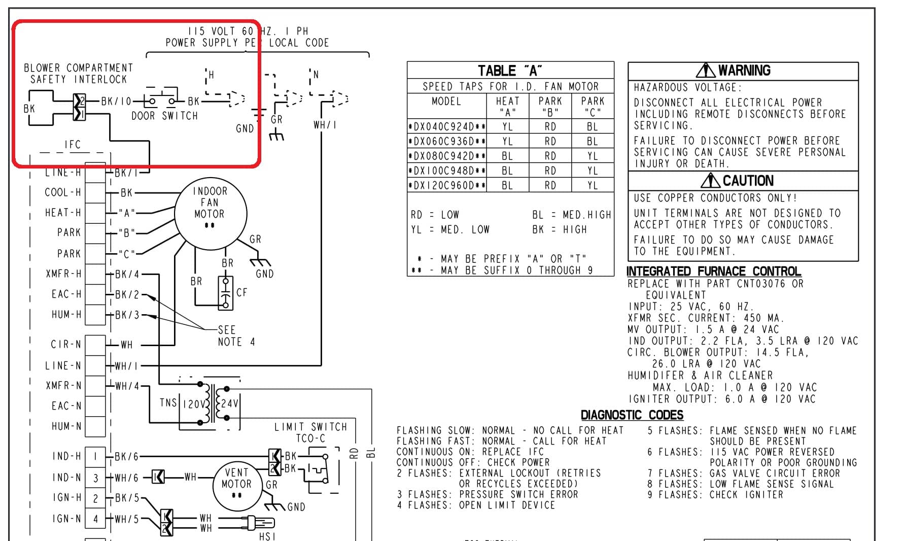
Furnace Interlock Wiring Diagram

12 Volt 2 Way Switch Wiring Diagram, How to wire LED Lights & Use 2-Way switches | 12 Volt Planet, 7.8 MB, 05:41, 128,538, 12 Volt Planet TV, 2019-03-07T10:24:09.000000Z, 19, 12v Switch Wiring, www.chanish.org, 600 x 555, jpeg, 12vdc oznium volts dimmer chanish, 20, 12-volt-2-way-switch-wiring-diagram, Anime Arts
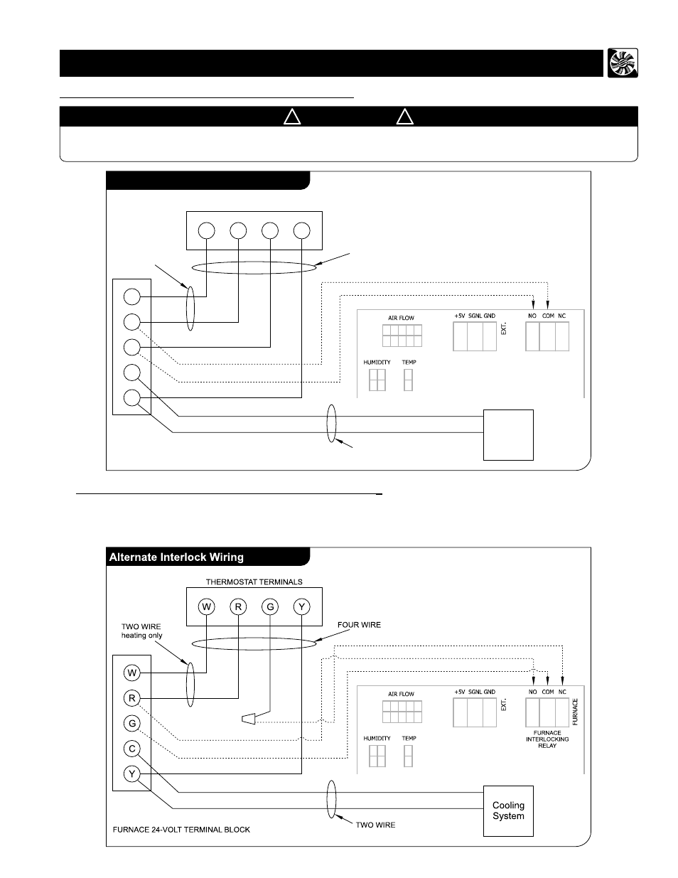
Furnace interlock in the fm takes the thermostat’s g terminal out of the circuit whenever there is a call for the energy recovery ventilator to operate. This schematic applies to ev90, ev130, ev200 and ev300 models. The percentage timer control with indicator lights and furnace interlock (fm) is the primary control for renewaire energy recovery ventilator (erv) models ev90, ev90p, ev130, ev200, ev240, ev300, ev premium, and sl70. Wiring options 1 and 2:
Exhaust fan interlock wiring diagram. Appliance wiring material is a classification of underwriters laboratories inc covering insulated wire and cable intended for internal wiring of appliances and equipment. You need a 3 way switch for the exhaust fan 2 way for the ventilation switch. Ford 9n wiring diagram. 17 pictures about ford 9n wiring diagram : Ford 9n wiring diagram www. tankbig. com. 9n wiring diagram ford harness tractor wire. Baseboard heater wiring questi. Here is the wiring as it has been done (two wires go to furnace and one wire goes to thermostat):
Furnace interlock, Alberta - Electrician Talk - Professional Electrical Contractors Forum

Wiring diagram (cont’d), Furnace / fan-coil / heat pump interlock, For a furnace connected to a

Exhaust Fan Interlock Wiring Diagram

Exhaust Fan Interlock Wiring Diagram

Burner Management System Logic and Interlock - InstrumentationTools

Bathroom Fan Furnace Interlock • Cabinet Ideas

Hrv Wiring Diagram
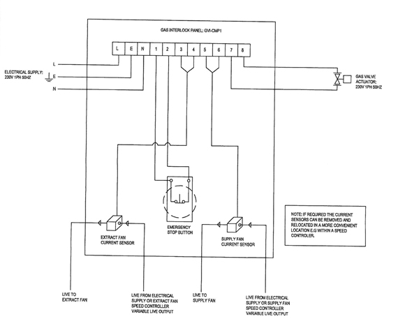
NCSP Gas Ventilation Interlock Panel / NFAN Supply & Stock Extractor Fans & Ventilation

New Ignition Module, Wiring Question. — Heating Help: The Wall

HRV Wiring - HVAC - DIY Chatroom Home Improvement Forum
