Ground Fault Breaker Wiring Diagram

12 Volt 2 Way Switch Wiring Diagram, How to wire LED Lights & Use 2-Way switches | 12 Volt Planet, 7.8 MB, 05:41, 128,538, 12 Volt Planet TV, 2019-03-07T10:24:09.000000Z, 19, 12v Switch Wiring, www.chanish.org, 600 x 555, jpeg, 12vdc oznium volts dimmer chanish, 20, 12-volt-2-way-switch-wiring-diagram, Anime Arts
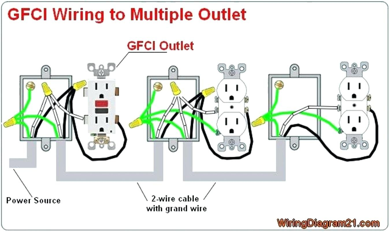
Ground fault circuit breaker wiring diagram from a. sellpoint. net effectively read a wiring diagram, one provides to find out how typically the components within the method operate. For instance , when a module is usually powered up also it sends out a new signal of 50 percent the voltage and the technician would not know this, he would think he provides a problem, as this. Gfci wiring outlets diagram circuit multiple ground fault outlet receptacles interrupter electrical diagrams series yourself help receptacle installing instructions duplex. Outlet afci leviton install diagram wiring wire connect grounding terminal bare copper.
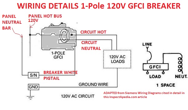
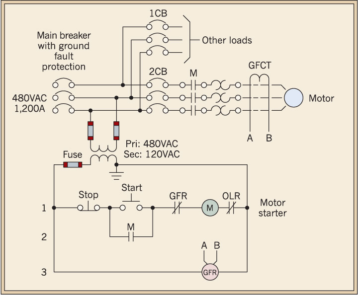
Connect the hot circuit wire to the hot or load screw terminal on the breaker, using a screwdriver. Connect the neutral circuit wire to the neutral screw terminal on the breaker. Connect the breaker's coiled white neutral wire to the neutral bus bar on the service panel. Ground fault plug wiring diagram wiring diagram is a simplified up to standard pictorial representation of an electrical circuit. $ gftcb eaton cutler hammer 2 pole 20 amp gfci breaker. The white wire is used for hot in this circuit and it is marked with black tape on both ends to identify it as such. Gfci circuit breaker definition. A ground fault breaker or gfci circuit breaker is a special circuit breaker that protects the entire circuit. It means that all the receptacles currently linked to the circuit with the gfci breaker have its protection.
Ground-Fault-Circuit-Breaker-and-Electrical-Outlet-Wiring-Diagram.png (1225×879) | death by

GFCI (Ground Fault Circuit Interrupter) vs. Circuit Breaker | Another Perfect Pool News
Ground Fault Circuit Interruptors, GFCIs Definition Peformance Electrical Codes

What is GFCI and How it Works? Ground Fault Circuit Interrupter | Gfci, Repair, Electricity

220 vokt ground fault breaker - Electrician Talk - Professional Electrical Contractors Forum
Ground Fault Receptacle Wiring Diagram Download - Wiring Diagram Sample

How To Wire An Electrical Outlet Uk Cleaver Ground Fault Circuit Breaker, Electrical Outlet

Ground Fault Breaker Wiring Diagram

Wiring A Ground Fault Breaker | MyCoffeepot.Org

220 Ground Fault Breaker Wiring Diagram - Wiring View and Schematics Diagram
